Internet of Things: Cellular Networks and Communications Evolution
Slides from M.sc. Computer Science about Internet of Things. The Pdf explores the evolution of communications, from landlines to modern cellular networks, explaining fundamental concepts of cells and their organization. This University level Computer science material is suitable for students.
See more44 Pages

Unlock the full PDF for free
Sign up to get full access to the document and start transforming it with AI.
Preview
Internet of Things
Cellular Networks
M.Sc. Computer Science 2024-2025 Viviana Arrigoni
Before Cellular Networks
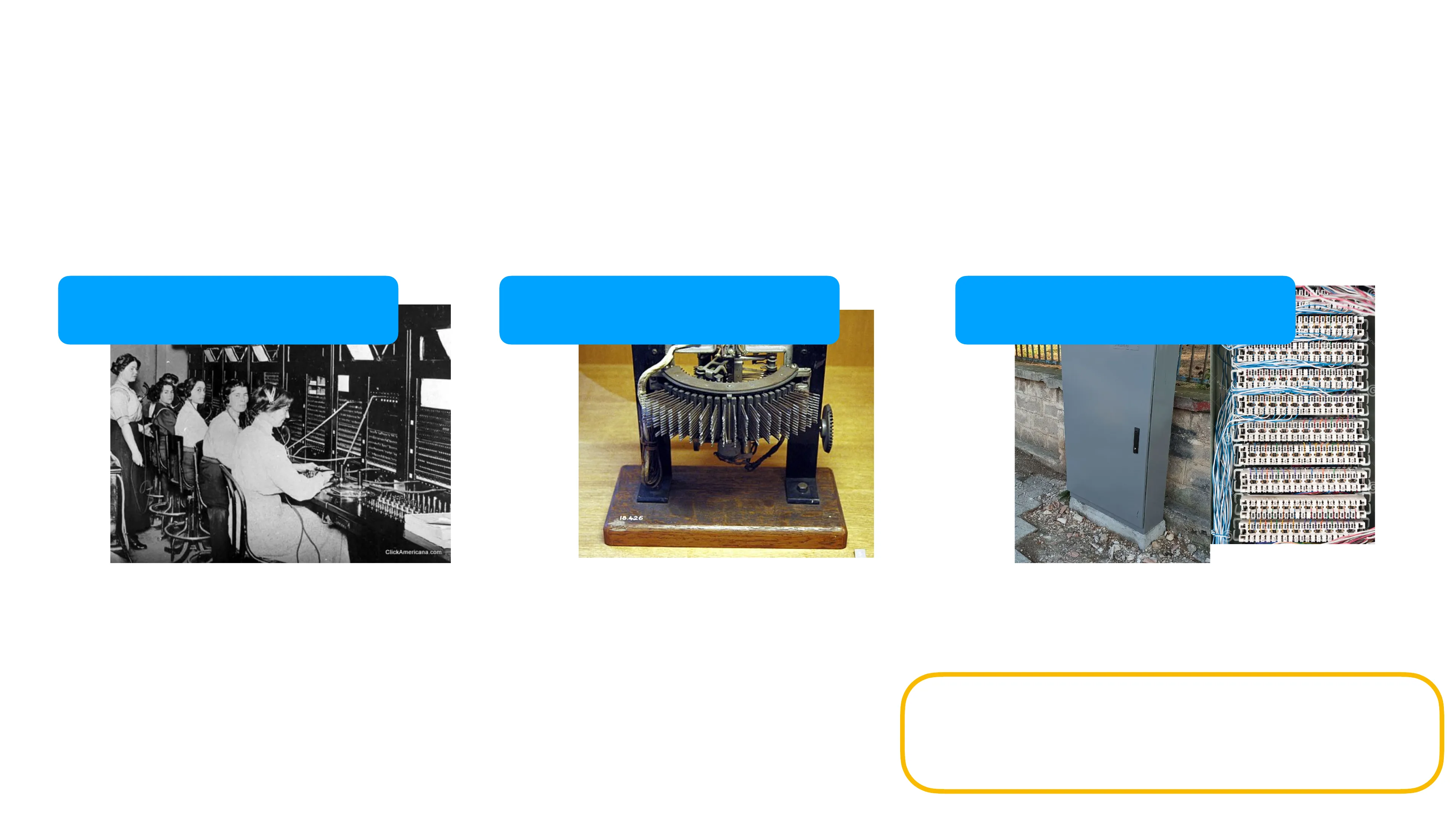
Before the introduction of cellular networks, only landline telephone connections existed.
Manual telephone exchanges
ClickAmericana.com. Telephone operators late 1800s - early 1900s. As you lifted the handset, you were connected to an operator at the exchange, who would plug your line into the line of the person you wanted to call using a switchboard. You had to give to the operator the number or the name of the person you wanted to reach.
Automatic exchanges
18.426 Electromechanical automatic switching systems. You would dial a number and the switch would move mechanical contacts to connect your line to the destination.
Digital exchanges (today)
When you dial a number, digital signals are routed using digital switching systems Only used for voice, i.e., only for analog signals
1G Cellular Networks
- First Generation (1G) cellular networks were the first cellular networks, introduced in the 1979.
- Purely analog cellular systems.
- No support for encryption, poor sound quality.
- Very limited coverage and data rate. Very few people were using this technology in their every day life. ...
2G Cellular Networks
- Beginning 1990s, second generation (2G) cellular networks superseded 1G.
- Introduced the concept of digital modulation: voice was converted into digital code, and then into analog (radio) signals.
- Based on the GSM standard (Global System for Mobile Communications), designed in Europe to establish a common standard for digital cellular voice communication.
- Did not support just voice calls, but also Short Messaging Service (SMS).
3G Cellular Networks
- Born in 2000, represented a real revolution: 3G cellular data networks connected devices not only to the existing cellular voice network, but also to the public Internet!
- Increased data rate.
Mobile and landline phone subscriptions per 100 people, 1960 to 2023
Our World in Data Landline (fixed telephone) Mobile United States United Kingdom 150 100 50 0 1960 1970 1980 1990 2000 2010 2023 1960 1970 1980 1990 2000 2010 2023 China India 150 - 100 50 0 1960 1970 1980 1990 2000 2010 2023 1960 1970 1980 1990 2000 2010 2023 Ghana Nigeria 150 100 50 0 1960 1970 1980 1990 2000 2010 2023 1960 1970 1980 1990 2000 2010 2023 Data source: International Telecommunication Union (via World Bank) (2025) ourworldinata.org/technological-change | CC BY
Cellular Concept
7.1 Cellular concept
- Landline telephones used high-powered base stations to cover large regions.
- Very few transmitters per area unit, often used dedicated channels for each user, limiting scalability.
- Cellular concept: divide the area into many smaller "cells", each covered by low- power transmitters and receivers, "Base Stations", BS.
- High capacity in a limited spectrum allocation
- Each BS is allocated portion of the total number of channels available
- Neighbouring BSs are assigned different groups of channels to minimise inferences
Cells (1)
- Cells are geographical areas covered by base stations.
Tessellation
Ideal cell Actual cell Different cell models Uncovered areas Overlapping areas (interferences may happen here) Hexagons approximate circles much better
Cell (2)
- Honeycomb grid (i.e., representation of each cell as a hexagon) is the model typically used for for theoretical representation of area division in cellular networks.
Cell (2) Honeycomb Grid
- Honeycomb grid (i.e., representation of each cell as a hexagon) is the model typically used for for theoretical representation of area division in cellular networks.
- In reality, the coverage area looks more like this: Overlapping and uncovered areas are still there. Still, honeycomb is the most used model and the one we will stick with
Frequency Reuse
- Frequency reuse or frequency planning consists in separating the frequency bands into sub-bands (i.e., different channels), and assign the same frequencies to different base stations (i.e., cells) that are distant enough.
- Avoid collisions between neighbouring cells CLUSTER
Frequency Reuse Bands
- Frequency reuse or frequency planning consists in separating the frequency bands into sub-bands (i.e., different channels), and assign the same frequencies to different base stations (i.e., cells) that are distant enough.
- Avoid collisions between neighbouring cells
Frequency Reuse Collisions
- Frequency reuse or frequency planning consists in separating the frequency bands into sub-bands (i.e., different channels), and assign the same frequencies to different base stations (i.e., cells) that are distant enough.
- Avoid collisions between neighbouring cells
Cluster Sizes
- A cluster of cells is a group of N cells such that the resulting shape of the cluster is tesselable.
- Within each cluster, all cells are associated with different frequencies.
- A cluster of N cells can be built if 3i, j E Ns . t . N = i2 + ij + j2
- N is the cluster size.
- Possible values of N are 1,3,4,7,9, ...
Co-cells/co-channels
(same frequency band)
- The reuse distance D is the minimum distance between two cells using the same frequency band.
- D = 13Nr, where r is the radium of the hexagon and N is the cluster size (proof omitted).
- q = = = 13N is called reuse factor.
- Low reuse factor (small N, large r) is best for rural areas or low-density networks. - less interference and capacity
- Large reuse factor (large N, small) best for dense, urban area. - more interference and capacity
- Total number of available radio channels in a cluster: S = kN, where
- k is the number of channels per cell, N is the cluster size.
- If the cluster is repeated m times in a area, then the total number of channels is mS = mkN
Cell Sectoring
- If the reuse distance D is not big enough, then two co-channels can interfere with one another.
- One possible solution is placing directional antennas at each cell. They virtually divide the cell into sectors.
- In 3-cell sectoring, the frequency band of the cell is divided into 3 sub-bands. One directional antenna uses one such sub-bands, and directs signals towards its direction.
- The round angle is split into three angles of 120° each, dividing the cell into three sectors, one for each antenna.
- Less interference between co-cells.
- Better isolation.
- More frequency reuse
- Lower power needs
Cell Splitting
- What do we do if the demand for more data rate increases in a region (e.g., an area gets more densely populated with the passing of the years)?
- Split existing cells by adding more base stations to provide more data rate. Depending on traffic conditions, smaller antenna cells may be activated or deactivated for better resource usage.
Cell Density
Large cell (low density) Small cell (high density) Smaller cell (higher density)
4G LTE
7.2 4G LTE
Elements of the 4G LTE architecture
Mobile device Mobility Management Entity (MME) Home Subscriber Service (HSS) Base station to Internet PDN gateway (P-GW) Serving Gateway (S-GW) radio access network - all-IP Enhanced Packet Core (EPC) · Based on LTE (Long-term evolution) standard. · Entirely IP-based, even for voice (VoIP/VoLTE). · Orthogonal Frequency Division Multiple Access (OFDMA) and Multiple Input Multiple Output (MIMO). · Higher data rates. · IoT applications. · LPWA-based licensed band technology.
Mobile Device
- Smartphones, tablets, laptops, or IoT devices that connect to a cellular network.
- Applications such as web browsers, map apps, voice and videoconference apps, mobile payment apps etc are run on mobile devices.
- Each mobile device is a network endpoint, with an IP address.
- Each mobile device also has a global unique 64-bit identifier called the International Mobile Subscriber Identity (IMSI), which is stored on its SIM (Subscriber Identity Module) card.
- The SIM card also stores information about the services that the subscriber is able to access. They depends on the "home network" or network operator of the SIM card.
Base Station
- The base station (BS) is a fixed station that covers an area. It consists of transmitter and receiver antennas mounted on a cell tower.
- A BS is responsible for managing the wireless radio resources and the mobile devices with its coverage area.
- Mobile device interact with a base station to attach to the carrier network (i.e., the internet or the telephone line), similarly to access points in WLANs.
- They provide the connection from the mobile devices to gateways, interact among themselves to handle device mobility among cells and minimize interference between cells. They are connected with one another through cables - no wireless.
Home Subscriber Server
- The Home Subscriber Server (HSS) is a database, storing information about the mobile devices for which the HSS's network is their home network.
- It is used in conjunction with the Mobility Management Entity (MME) for device authentication.
Network Routers
- Serving Gateway (S-GW) and the Packet Data Network (P-GW) Gateway are two routers (often collocated in practice) that lie on the data path between the mobile device and the Internet.
- The Packet Data Network Gateway provides IP addresses to mobile devices.
- To the outside world, the P-GW looks like any other gateway router.
- The Serving Gateway routes and forwards user data packets
Mobility Management Entity (MME)
- The Mobility Management Entity (MME) serves to authenticate a device wanting to connect into its network.
- After receiving an attach request from mobile device, the local MME contacts the home subscriber server in the mobile's home network. ..
MME Authentication
Mobility Management Entity (MME) Mobile device Home Subscriber Service (HSS) Base station
Mobility Management Entity (MME) Authentication
- The Mobility Management Entity (MME) serves to authenticate a device wanting to connect into its network.
- After receiving an attach request from mobile device, the local MME contacts the home subscriber server in the mobile's home network.
- The mobile device receives encrypted data confirming that the home HSS is performing authentication through this MME. This MME is used for authentication
MME Authentication Process
Mobility Mobile device Management Entity (MME) Home Subscriber Service (HSS) Base station
Can’t find what you’re looking for?
Explore more topics in the Algor library or create your own materials with AI.
