Sheet Metal Forming: Principles of Blanking and Drawing Processes
Slides from Mondragon Unibertsitatea about Sheet Metal Forming. The Pdf provides an introduction to sheet metal forming, detailing blanking and drawing processes, including formulas for initial blank dimensions. This University level Technology material is suitable for engineering students.
See more65 Pages


Unlock the full PDF for free
Sign up to get full access to the document and start transforming it with AI.
Preview
Mondragon Unibertsitatea Faculty of Engineering
Sheet Metal Forming Introduction
Mondragon Unibertsitatea Faculty of Engineering Sheet metal forming refers to those processes in which forming and cutting operations are performed on metal sheets, strips and coils. In contrast with the bulk metal deformation the sheet metal forming is based on a high Surface area-to-volume ratio starting material. Generally performed in cold regime, they are usually accomplished using a set of tools called "punch" and "die".
Advantages of Sheet Metal Forming
- Massive part production / Low unitary cost.
- Good surface quality & dimensions.
- Good mechanical properties.
Introduction to Sheet Metal Forming
Mondragon Unibertsitatea Faculty of Engineering
Typical Sheet Metal Applications
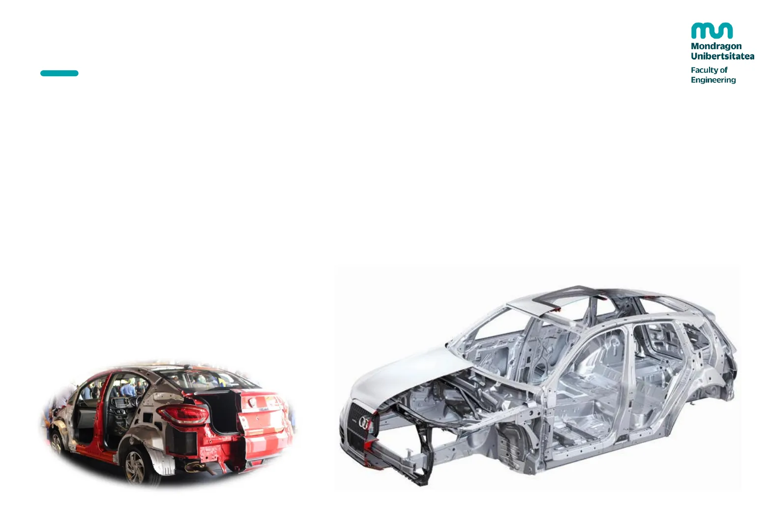
- Automotive structure Osmore
- Aeronautics & Aerospace
- Computer & Electronics
- Construction
- Consumer goods
https://www.youtube.com/watch?v=P7fi4hP_y80 https://www.youtube.com/watch?v=Saz03u851HQ https://www.youtube.com/watch?v=5WikP_Fk2v4 https://www.youtube.com/watch?v=4WpGsJKVhZY
Introduction to Sheet Metal Operations
Mondragon Unibertsitatea Faculty of Engineering
Three Main Sheet Metal Operations
- Cutting
- Shearing: straight line cutting of large sheets.
- Punching: making holes in the sheet part.
- Blanking: cutting of the part perimeter in the sheet part.
- Bending: straining around a straight axis each of the sides next to the neutral axis.
- Drawing: sheet metal forming operation used to make cup-shaped, box-shaped or other complex-curved and concave parts.
30mn Mondragon Unibertsitatea Faculty of Engineering
CUTTING
Mondragon Unibertsitatea Faculty of Engineering
Cutting - Blanking Examples
Example - Blanked parts
O 00 10 11 2 5 1 7 3 17 18 12 4 13 9 6
Cutting - Blanking Tooling
Mondragon Unibertsitatea Faculty of Engineering Example - Blanking-Piercing tooling :
Cutting Procedure
Mondragon Unibertsitatea Faculty of Engineering Cutting of sheet metal is accomplished by shearing action between two sharp cutting edges. The figure below depicts the cutting procedure:
- The upper cutting edge (the punch) sweeps down past a stationary lower cutting edge (the die).
- As the punch begins to push the material, plastic deformation occurs in the surfaces of the sheet.
- As the punch moves downward, penetration occurs in which the punch compresses the sheet and cuts into the metal (penetration zone ~1/3*t).
- As the punch continues, fracture is initiated at the two working edges until the final breakage.
v, F Punch Plastic deformation -c -Die (1) (2) V, F |V, F 1 Penetration Fracture (3) (4) Image taken from [1]
Cutting Surface Zones
Mondragon Unibertsitatea Faculty of Engineering As a result of the cutting procedure different zones can be distinguished in the surface of the material.
- Rollover: The upper edge is rounded as a consequence of the initial deformation provoked by the punch compression during the first stage of the metal cutting.
- Burnish: Here the surface is burnished because of the friction during the penetration of the punch.
- Fractured zone: When the remaining material is not able to withstand the force applied by the punch sheet fracture occurs.
- Bur: Because of the material fracture and plastic deformation a burr is formed in the trailing edge.
Rollover Burnish ť Image taken from [1] Fractured zone Burr
Cutting Types
Mondragon Unibertsitatea Faculty of Engineering
- Cutting types The three most important cutting processes are the following:
- Shearing: Typically used to cut large sheets into smaller sections for subsequent press-working.
- Blanking: It consists of cutting a sheet metal along a closed outline in a single step to separate the piece from the surrounding stock. The separated piece is the working material.
- Punching/Piercing: Similar to blanking except that it produces a hole, and the separated piece is scrap.
Shearing punch Die Strip (scrap) 4 Blank (part) Part Image taken from [1] Slug (scrap)
Nominal Dimension in Cutting
Mondragon Unibertsitatea Faculty of Engineering Depending on the type of cutting process performed the nominal dimension on the desired final part will be given by the punch or the die.
- Punching: the nominal hole dimension will be given by the punch
- Blanking: the nominal part dimension will be given by the die
Punch Sheet stock Dh= punch size Die C C +Db = die size Blanked piece Image taken from [1]
Cutting Tooling Dimensions
Mondragon Unibertsitatea Faculty of Engineering
- Tooling dimensions
- Distance between the die and the punch "u", j=2*u
- If t < 3 mm then, u = 0.005 . t . R.
- If t > 3 mm then, u = (0.01 . t - 0.015) . Rc
- If the desired part is the workpiece (piercing), the nominal size will be on the punch
- If the desired part is the blank (blanking), the nominal size will be on the die
- Tolerances depend on the required accuracy
Cutting Tooling Calculation
Mondragon Unibertsitatea Faculty of Engineering
- Tooling calculation
- Blanking steel:
- Sheet thickness = 1 mm
- Tensile strength = 36 kg/mm2
R10 ø10 50 70
Seeger Ring Fabrication
Mondragon Unibertsitatea Faculty of Engineering
- Seeger ring fabrication
Final blanking Positioning pin Blanking for positioning pin 1 3 2 Holes Blanking 8 Holes blanking detection Positioning pin Blanking for positioning pin
Cutting Force Calculation
Mondragon Unibertsitatea Faculty of Engineering
- Force calculation
- Three different forces have to be taken into account
- Pure cutting force (ER): Necessary force to shear the material
- Punch extraction force (Ex): Necessary force to extract the punch after cutting
- Ejection force (Eej): Necessary force to eject the cut part from the die
ER Eex Eej
Cutting Force (ER)
Mondragon Unibertsitatea Faculty of Engineering
- Cutting force (ER)
- This is the necessary force to overcome the strength limit of the material.
- Hence, it is calculated as follows: ER = P . t . Omat
- Where,
- "p" is the perimeter to be cut
- "t" is the thickness of the blank
- Omat is the shear strength of the material
ER
Punch Extraction Force (Eex)
Mondragon Unibertsitatea Faculty of Engineering
- Punch extraction force (Eex)
- It is the necessary force to extract the punch from the sheet due to the elastic recovery of the material
- The force depends on the remaining material around the punch
- It is usually given in terms of % of cutting force:
- For small cut/remaining > Eex = 7% ER.
- For a remaining material bigger than 3*t > Eex = 2-7% ER.
- For a normal remaining material > Eex = 2% ER.
O CC Small cut Remaining mat > 3*t Normal remaining mat Eex
Ejection Force (Eej)
Mondragon Unibertsitatea Faculty of Engineering
- Ejection force (Eej)
- It is also usually given in percentage of the cutting force: Eej = 1,5% ER
Eej
Shape Optimization in Cutting
Mondragon Unibertsitatea Faculty of Engineering
- Shape optimization
- It is very important the rational use of the material to minimize the scrap
- Once the necessary material to get the part is defined, the positioning of the shape on the coil should be optimized > maximize the use of the material
- The use of material is measured on percentage as follows: Use of material = Part surface Used surface × 100
- The used surface is calculated as follows:
- Used surface = with of the coil (B) * separation distance (p)
- Therefore, smaller "p" means a better use of material
p LLL B p
Shape Optimization Restrictions
Mondragon Unibertsitatea Faculty of Engineering
- Shape optimization - Restrictions
- There are some gap dimensions that have to be respected for the correct use of the set- up
Material Thickness (mm) Cutting Width smaller than 10 mm Cutting Width between 10 mm and 80 mm Bigger than 80 mm 0.2-0.4 1.0 1.5 2.5 Steel 0.4-0.6 0.6 1.0 1.5 0.6-1.0 0.8 1.5 2.0 1.0-1.5 1.0 2.0 2.5 1.5< 1 s 1.2 s 1.5 s Al 0.2-0.5 2.0 3.0 4.0 0.5-1.0 1.0 2.0 3.0 1.0-1.5 1.5 2.5 3.5 1.5< 1.2 s 1.5 s 2.0 s
Shape Optimization - Typical Set-ups
Mondragon Unibertsitatea Faculty of Engineering
- Shape optimization - Typical set-ups 1) Horizontal arrangement 51 2) Vertical arrangement 36 4) Opposed arrangement 47 13 ES 5) Opposed tilted arrangement 26 $ R 3) Tilted arrangement 26 X 21 D 01 6) Offset arrangement
Mondragon Unibertsitatea Faculty of Engineering
BENDING
Bending Definition
Mondragon Unibertsitatea Faculty of Engineering
- It is defined as the straining of the metal around a straight axis, being under compressive and tensile loading each of the sides next to the neutral axis (see figure).
- The metal is plastically deformed in order to create a permanent deformed shape.
- Bending produces little or almost no change in the thickness of the sheet metal.
F, v Punch Work Die Metal stretched Neutral axis Metal compressed Image taken from [1] Bending > https://www.youtube.com/watch?v=xSB_z4JVPIk
Bending Parameters
Mondragon Unibertsitatea Faculty of Engineering
- The metal of thickness "t" is bent through an angle "a" called the bend angle.
- This results in a sheet-metal part with an included angle a', where a+ a'=180º.
- The bend radius "R" is normally specified on the inside of the part, rather than at the neutral axis, and is determined by the radius on the tooling used to perform the operation.
- The bend is made over the width "w" of the workpiece
1 W Neutral axis plane R Tt Bend axis Image taken from [1]
Bending Radius Considerations
Mondragon Unibertsitatea Faculty of Engineering
- If the bending radius R is small relative to the sheet thickness, the metal tend to stretch and crack during bending.
- If the bending radius R is big relative to the sheet thickness, the metal suffers a great elastic recovery.
- In both cases, the final component and dimensional accuracy is compromised
- Recommendations:
- Avoid sharp angle bending
- Minimum radius R=t.
- Maximum radius R=5t
Springback in Bending
Mondragon Unibertsitatea Faculty of Engineering
- Springback The elastic recovery after the deformation is called "Springback"
- It depends on the material properties (Modulus of elasticity (E) and Yield strength (Re))
Punch Pad Die Start During Final Springback b 0 a 1 d C ɛ
- Main way to overcome it > The overbending
- It consists of using slightly smaller radius and angle in the punch and dies so as to meet the dimensions after the elastic recovery.
Initial Blank Dimensions for Bending
Mondragon Unibertsitatea Faculty of Engineering
- Initial blank dimensions
- Before bending the part, it has to be calculated the initial blank dimensions.
- As the neutral fiber does not deform, its length will define the initial blank dimensions.
- Assuming that the previous steps have been properly performed, no stretching is supposed to occur.
- However, to calculate the initial dimensions, the following equation and { radius correction factor is used: + πα 180 ·(R+5.5) R/t 5 3 2 1.2 0.8 0.5 ξ 1 0.9 0.8 0.7 0.6 0.5
- Lz: initial blank dimensions
- ai: flat surface length
- a: bending angle
- R: inner bending radius
- t: thickness
- ¿: correction factor
Can’t find what you’re looking for?
Explore more topics in the Algor library or create your own materials with AI.