Erd: introduzione ai diagrammi Entity Relationship per database
Slide di Università su Erd. Il Pdf introduce i diagrammi ERD (Entity Relationship Diagrams), spiegando la loro funzione nella rappresentazione delle strutture di database e illustrando i concetti chiave degli attributi, con esempi pratici e simbologia per Informatica.
Mostra di più30 pagine


Visualizza gratis il Pdf completo
Registrati per accedere all’intero documento e trasformarlo con l’AI.
Anteprima
ERD
Entity Relationship Diagrams
Che cos'è un ERD?
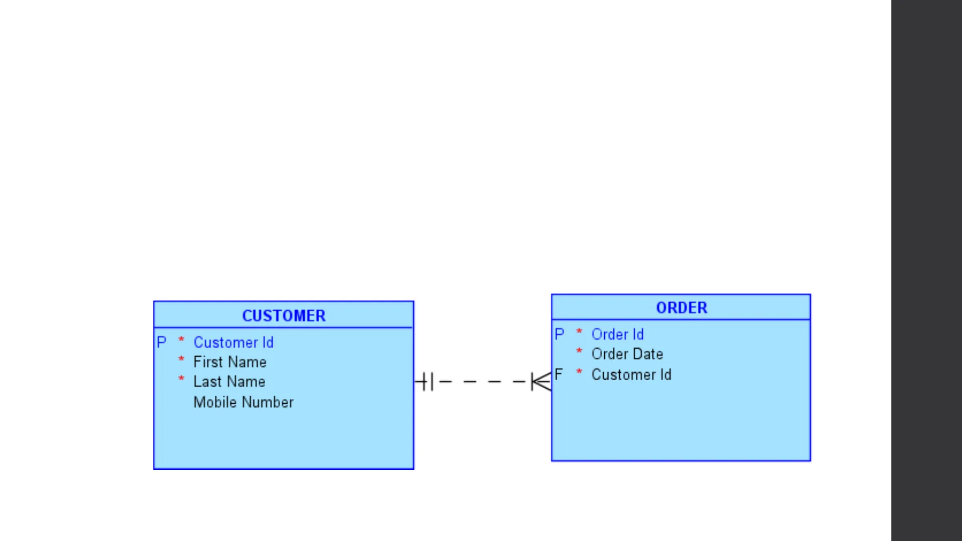
- Un ERD è un diagramma logico che rappresenta la struttura di un database utilizzando il modello relazionale.
- Esempio - ERD che mostra un'entità Cliente, un'entità Ordine e la relazione tra di esse.
CUSTOMER ORDER P * Customer Id P * Order Id First Name * Order Date * Last Name Mobile Number +1- - V 1 I F * Customer Id
Applicazione richiesta
- Per disegnare l'ERD - è richiesto Oracle SQL Developer Data Modeler. È possibile scaricarlo da http://www.oracle.com/technetwork/developer-tools/datamodeler/overview/index.html
Cloud Computing ORACLE SQL Developer Data Modeler
Configurazione di Data Modeler
- Estrarre il contenuto del file zip di Data Modeler (non è necessario installarlo).
- Eseguire datamodeler64.exe
Browser x ?) St Designs [1] Untitled_1 + Logical Mode! Multidimens Show Relational M Hide A Domains [1] + Data Types Create SubView + Process Mor + Business In Create Display ...
- Right Click on Logical Model
- Click on Show
Configurazione di Data Modeler
File Edit View Team Tools Help A Editor Show Status Bar Browser ? Start Page x Logical (Untitled_1) Designs Browser Alt-B Untit Navigator Alt-N + Log Alt-L + External Log Ctrl-E + A + Files + ... Logical Diagram Notation A View Details DDL Preview Alt+Shift-I Barker Notation Bachman Notation Information Engineering Notation
- Click on View from the Menu
- Click on Logical Diagram Notation
- Choose Information Engineering Notation
Configurazione di Data Modeler
Undo Move PERSON Redo Undo to Redo to Paste PERSON erson ID Integer ccount ID Integer Layout View Details v All Details Hide Details On Zoom Out Notation A Classification Types Go To Diagram A Show Dynamic Properties Comments Views Print Diagram A Names Only Attributes nv CV LIV AuLILA __ ALL.
- Click on View Details
- Make sure that All Details are chosen
Diagram
Concetti ERD - Entità
- Un'entità è un oggetto che può essere identificato autonomamente e fa parte dell'intera soluzione. Ad esempio, la progettazione di un database per una Collezione Musicale
- Album è un'entità
- Artista è un'entità
- Quando si implementa un database in SQL, un'entità diventerebbe una tabella/
- Un'istanza di entità è un record all'interno di una tabella.
CLIENT
Concetti ERD - Entità
- Un'entità è disegnata come un rettangolo.
- Il nome dell'entità è racchiuso al centro in alto del rettangolo.
- Il nome dell'entità dovrebbe essere in maiuscolo.
- Il nome dell'entità dovrebbe essere in forma singolare.
CLIENT Entity Properties - Entity_2 ...... General ..... Attributes .... Unique Identifiers Relationships Name: CLIENT Subtypes ... Volume Properties Short Name: .Enningar TA
Concetti ERD - Attributo
- Un attributo è una proprietà di un'entità che descrive le caratteristiche di una particolare istanza di entità. Un attributo può essere di tre tipi:
- Unique Identifier - Un UID è un attributo il cui valore identifica in modo univoco un'istanza di entità. Un UID è implementato come chiave primaria.
- Attributo Obbligatorio: Un attributo il cui valore non può essere nullo.
- Attributo Opzionale: Un attributo il cui valore può essere nullo.
CLIENT P * UID * Mandatory Optional
Concetti ERD - Attributi
- Gli attributi devono avere un nome significativo.
- La prima lettera di ogni parola dovrebbe essere maiuscola e il resto minuscola.
Details Overview Attributes: Name + x Name Data type 1 Attribute_1 Unknown Attribute Properties Name: Attribute_1 Datatype: Domain Logical Distinct Structured Collection Unknown Preferred Primary UID Relation UID Mandatory Deprecated CLIENT P * UID * Mandatory Optional Type:
Concetti ERD - Attributo
Details Overview Attributes: Name + Name Data type 1 Attribute_1 Unknown Attribute Properties Name: 1 Attribute_1 Datatype: Domain Logical 2 Distinct Structured Collection Type: 3 Unknown Preferred 4 5 Primary UID Relation UID Mandatory Deprecated
- Number
- Description
- Name of the attribute.
- This must be chosen to allow the selection of standard data types.
- Select the desired data type (to use this, Logical must be selected in 2).
- Tick this to set the attribute as a primary key.
- If this is un-ticked, the attribute is optional; otherwise it will be mandatory (required).
Concetti ERD - Attributi
- Accanto a ogni attributo viene posizionato un simbolo che rappresenta il tipo di attributo.
Symbol Meaning * Mandatory (Required) P Primary Key F Foreign Key PF Primary and Foreign Key (Nothing) Optional CLIENT P * UID * Mandatory Optional
Concetti ERD - Relazione
- Una relazione collega due o più istanze di entità.
- Una relazione viene utilizzata collegando la chiave primaria con una chiave esterna.
CUSTOMER P * Customer Id * Order Date * Last Name Mobile Number +1- - F * Customer Id 1 1 V ORDER P * Order Id * First Name
Concetti ERD - Relazione
- Una relazione può esistere tra un massimo di due entità.
- Una relazione può esistere sulla stessa entità (relazione ricorsiva).
- Una relazione ha due prospettive.
Icon Type of relationship Many-to-many (shall not be used) One-to-many One-to-many with an identifying foreign key One-to-one
Concetti ERD - Relazione
Name: Relation 1 Use surrogate keys: Source Cardinality Target Cardinality Source: CUSTOMER Target: ORDER Source key: CUSTOMER.CUSTOM ... Target key: Name on Source: Name on Target: Source Entity Synonym: CUSTOMER Target Entity Synonym: ORDER V Source to Target Cardinality: ( * Target to Source Cardinality: -1 Transferable: Transfer Number Description Dominant Role: None V 3 Identifying: 4 Delete Rule: NO ACTION 2 Is target optional? (Yes/No) 3 In case of one-to-one relationship, which is the dominant table? i.e. which table's primary key will be used as a foreign key. 4 Is the foreign key identifying? Will the foreign key be used as a primary key? Source Optional: 1 Target Optional: 2 1 Is source optional? (Yes/No)
Relazioni - Forte e Debole
- Relazione Forte - la chiave esterna sarà utilizzata anche come chiave primaria.
CUSTOMER ORDER P * Customer Id P * Order Date PF* Customer Id * First Name * Last Name Mobile Number 1
- Relazione Debole - la chiave esterna non sarà utilizzata come chiave primaria.
CUSTOMER Order Id P * Customer Id * Order Date * First Name F * Customer Id * Last Name Mobile Number V ORDER
Cardinalità della relazione
- Quando si crea una relazione ci sono vari simboli che rappresentano la cardinalità di una relazione.
Symbol Cardinality 0 or 1 Exactly 1 0 or Many 1 or Many
Cardinalità della relazione - 1-M
- Un cliente può avere 0 o molti ordini
- Un ordine può essere correlato a 0 o 1 cliente
ORDER CUSTOMER P Customer Id P * Order Date * First Name F Customer Id * Last Name Mobile Number Q V
Cardinalità della relazione - 1-M
- Un cliente deve avere 1 o più ordini
- Un ordine può avere 0 o 1 cliente
ORDER CUSTOMER P * Customer Id P * Order Date * First Name F Customer Id * Last Name Mobile Number HG - - -
Cardinalità della relazione - 1-M
- Un cliente può avere 0 o molti ordini
- Un ordine deve essere correlato a un solo cliente
ORDER CUSTOMER P * Customer Id P * Order Date F * Customer Id First Name 41- -- 04 * Last Name Mobile Number
Cardinalità della relazione - 1-M
- Un cliente deve avere 1 o molti ordini
- Un ordine deve essere correlato a un solo cliente
ORDER CUSTOMER P * Customer Id P * Order Date * First Name F * Customer Id Last Name Mobile Number + 1 1
Cardinalità della relazione - 1-1
- Gli stessi concetti di una relazione Uno-a-Molti si applicano a una relazione Uno-a-Uno.
- Una relazione uno-a-uno specifica che un'entità può avere un solo record che corrisponde a un altro record univoco nell'entità correlata.
Cardinalità della relazione - 1-1
- Un cliente può avere zero o un account.
- Un account può essere correlato a nessuno o 1 cliente.
- In questo caso la chiave esterna dovrebbe essere posizionata nell'entità con il minor numero di righe/null o dove è più rilevante.
CUSTOMER ACCOUNT * Customer Id Account Id First Name Username Last Name Mobile Number * Password F Customer Id
Cardinalità della relazione - 1-1
- Un cliente può avere zero o 1 account.
- Un account deve essere correlato a un cliente.
- La FK dovrebbe essere posizionata nell'entità Account poiché non ci saranno mai valori NULL nella FK.
CUSTOMER ACCOUNT P * Customer Id P Account Id * First Name * Username * Last Name Mobile Number +1 --- O+ * Password F Customer Id
Cardinalità della relazione - 1-1
- Un cliente deve avere un account.
- Un account può essere correlato a zero o un cliente.
- La FK dovrebbe essere posizionata nell'entità Customer poiché non ci saranno mai valori NULL nella FK.
CUSTOMER ACCOUNT P * Customer Id * Account Id * First Name * Username * Last Name Mobile Number HO - - - I+ * Password F * Account Id
Cardinalità della relazione - 1-1
- Un cliente deve avere un account.
- Un account deve avere un cliente.
- La FK dovrebbe essere posizionata dove è più rilevante in base allo scenario poiché non sarà mai un valore NULL nella FK.
CUSTOMER ACCOUNT P * Customer Id P * Account Id * First Name * Username * Last Name Mobile Number +/- - - - -1+ * Password F * Account Id
Cardinalità della relazione - M-N
- Una relazione molti-a-molti non dovrebbe mai essere utilizzata nella progettazione di un database e dovrebbe essere risolta inserendo un'entità intermediaria (un'entità aggiuntiva che unisce le due entità).
GAME PLATFORM P * Game Id P * Platform Id Title Platform Name * Price -- 00 Discount
Cardinalità della relazione - M-N
GAME PLATFORM Game Id P * Platform Id * Title Platform Name * Price Discount This is resolved as follows. An intermediary entity is added having the primary key of each table as a foreign key. Two problems with this example: 1. A Game can be left out without a platform 2. The same game with the same platform can appear more than once. GAME GAME LIST PLATFORM P * Game Id P Gamelist Id P Platform Id Title F * Game Id * Platform Name * Price <F * Platform Id >0 - - - It Discount - - - - -04
Cardinalità della relazione - M-N
GAME PLATFORM P Game Id 0 Platform Id * Title * Platform Name * Price 1 1 1 7 This is resolved as the previous example, but a game must be related to at least one platform. In this case we're left with one problem: 1. The same game with the same platform can appear more than once. GAME GAME LIST PLATFORM Game Id P * Gamelist Id P Platform Id Title F * Game Id * Platform Name * Price F * Platform Id 1 - - |+ Discount 1 1 V Discount
Non hai trovato quello che cercavi?
Esplora altri argomenti nella Algor library o crea direttamente i tuoi materiali con l’AI.
