HAWT Design Basics: Aerodynamic Theory and Ideal Blade Shape Definition
Slides from Università Degli Studi Firenze about HAWT design basics. The Pdf, a presentation for University Physics students, covers aerodynamic theory, ideal blade shape definition, and aeroelastic design of wind turbine blades, as outlined in the document.
See more20 Pages


Unlock the full PDF for free
Sign up to get full access to the document and start transforming it with AI.
Preview
HAWT Design Basics Theory Recap
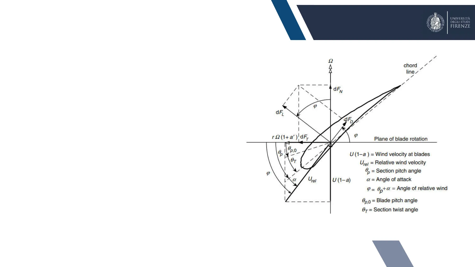
For a lift-driven rotor like a HAWT the relative velocity (Urel) is a function of the blade velocity at the radius under consideration and approximately two thirds of the wind velocity (Betz theory) With respect to plane of rotations, the relative airflow has an angle of relative wind (0) given by the sum of the three angles:
- section twist angle (07)
- blade pitch angle (0po)
- aerodynamic angle of attack (a)
2 chord line I dFN - - - - dF dF. r 2 (1+ a' )!dF, Plane of blade rotation 1 p.0 U (1-a ) = Wind velocity at blades OT - Urel = Relative wind velocity p = Section pitch angle Urel U (1-a) a = Angle of attack P = 0p+a = Angle of relative wind @p,o = Blade pitch angle OT= Section twist angle 2 STU DIORUM . UNIVERSITÀ DEGLI STUDI FIRENZE Wind and Marine energy . FL
HAWT Blade Design
UNIVERSITBlade Design STU Wind and Marine energy DIORUM +1 UNIVERSITÀ DEGLI STUDI FIRENZE UNIVERSITA HAWTs are very sensitive to changes in blade profile and design The main parameters that influence the performance of HAWT blades are :
- Tip Speed Ratio (TSR) and design wind speed
- airfoil selection (Cldesign and @ design)
- chord distribution and staggering (twist angle)
- pitch angle
Turbine Design Process
3Turbine design process Wind and Marine energy STU + FL UNIVERSITA +Sull regulated - Dynamic condition Pitch regulated - Dynamic condition Cateraar power |kvc] Generator Torque (Nm) region 2-1/2 rated torque rated region 2 speed region 1 Generator speed (rpm) 2.0 Aerodynamic coefficient [-] 0.8 0.4 0.0 -04 -0.8 12 -180 -150-120 -90 -60 -30 0 30 60 90 120 150 180 Angle of attack [deg] Ideal blade shape definition (aerodynamically and structurally) THICK-AIRFOIL FAMILY FOR MEDIUM BLADES TIP-REGION AFFOL, 15% RADIUS PRIMARY OUTBOARD AIRFOR, 78% RADIUS Cl & Cd calculation ROOT-REGION AUFOIL, AI'S RATHUIS Airfoil selection 1 Turbine specification definition The design loop method is based on an iterative trial-and-error method, thus each desing solution is analyzed either aerodynamically and structurally at each iteration 4 Steady/Turbulent State performance evaluation Controller tuning 12 Wind velocity |m/s] FINAL DESIGN DIORUM + UNIVERSITÀ DEGLI STUDI FIRENZE region 3Turbine specification
Power Target and Rotor Swept Area
Definition of power target, TSR and wind speed design, turbine class & control strategies is key Power target and rotor swept area
| Swept Area [m2] | Rotor Diameter [m] | Approximate Power Rating Expected @11m/s [kw] | Load Assessment/Validation Requirement Category |
| 1 | 1.13 | 0.245 | Micro - XS No Loads Analysis Required |
| 2 | 1.6 | 0.489 | |
| 5 | 2.5 | 1.22 | |
| 10 | 3.6 | 2.45 | |
| 50 | 8.0 | 12.2 | Small - S SLM/AM with minimum validation |
| Current IEC | |||
| 200 | 16.0 | 49.0 | Medium - M AM with extensive validation |
| 300 | 19.5 | 73.4 | |
| 500 | 25.2 | 122 | |
| >500 | >25.2 | 120< power <600 | Large - L |
Turbine Class Definition
Turbine class A wind turbine class is defined in terms of reference wind speed and turbulence intensity
| Turbine class | I | II | III |
| Vref ( m/s) | 50 | 42.5 | 37.5 |
| A Iref | 0.16 | ||
| B Iref | 0.14 | ||
| C Iref | 0.12 |
Turbulence standard deviation (m/s) 4.0 50 3.5 40 3.0 2.5 30 2.0 20 1.0 10 20 30 10 20 30 Wind Speed (m/s) Wind Speed (m/s)
Control Strategies
Control strategies
- PITCH CONTROL
- STALL CONTROL
5 UNIVERSITÀ DEGLI STUDI FIRENZE Wind and Marine energy + FLOR DIORUM + UNIVERSITA STU Turbulence Intensity (%) 1.5 100 11.3 24.5
TSR and Design Wind Speed
.4.5TSR and design wind speed TSR is the foremost design parameter around which all other optimum rotor dimensions are calculated Qr W À = Tip speed ratio Q= Rotational velocity (rad/s) r = Radius Vw = Windspeed Aspects such as efficiency, torque, mechanical stress, aerodynamics and noise should be considered in selecting the appropriate TSR (since it directly determines w v high TSR makes centrifugal stresses increase and aerodynamics more critical Y high TSR decreases blade solidity and increase aerodynamic noise v modern rotors generally operate with TSR between 5 and 10
Tip Speed Ratio Comparison
| Low | High | |
| Value | Tip speeds of one to two are considered low | Tip Speeds higher than 10 are considered high |
| Utilisation | traditional wind mills and water pumps | Mainly single or two bladed prototypes |
| Torque | Increases | Decreases |
| Efficiency | Decreases significantly below five due to rotational wake created by high torque | Insignificant increases after eight |
| Centrifugal Stress | Decreases | Increases as a square of rotational velocity |
| Aerodynamic Stress | Increases proportionally with rotational velocity | Decreases |
| Area of Solidity | Increases, multiple 20+ blades required | Decreases significantly |
| Blade Profile | Large | Significantly Narrow |
| Aerodynamics | Simple | Critical |
| Noise | Increases to the 6th power approximately |
STU Wind and Marine energy + FLOR DIORUM + UNIVERSITÀ DEGLI STUDI FIRENZE UNIVERSITA 6
Airfoil Selection
Airfoil selection The selection of the airfoils plays a crucial role in the aerodynamic design process Several databases do exist (NREL, Risø, Delft etc.) with airfoils designed and simulated for different wind energy applications The shape of the airfoils to be selected is always a compromise between performance, regulation characteristics (especially important in stall- regulated wind turbines), and structural stiffness STI DIORUM - UNIVERSITÀ DEGLI STUDI FIRENZE Wind and Marine energy + FL UNIVERSIT NACA 64-618 DU 93-W-210 DU 91-W2-250 Skin DU 97-W-300 DU 99-W-350 DU 99-W-405 Spar 7Airfoil selection The use of a single airfoil for the entire blade length would result in inefficient design V each section along the span has not only a different relative speed and AoA, but also structural requirements y airfoil need to be tailored accordingly At the root, the blade sections have large minimum thickness which is essential for the intensive loads to be managed resulting in thick profiles Approaching the tip, blades blend into thinner sections with reduced load, higher linear velocity and increasingly critical aerodynamic performance STU + FLOR DIORUM + UNIVERSITÀ DEGLI STUDI FIRENZE UNIVERSITA Lift to Drag Ratio = NACA 64-618 DU 93-W-210 Lift force DU 91-W2-250 Skir DU 97-W-300 Pitching moment Airflow DU 99-W-350 a Drag force DU 99-W-405 c/4 Chord Spar Wind and Marine energy Coefficient of lift Coefficient of drag Cp The general requirement for airfoil design is a high lift-to-drag ratio 8
Ideal Blade Shape Definition
Ideal blade shape definition The first approach to blade shape definition is usually made with BEM First, a design TSR (A), the blade number (B) the radius (R), and an airfoil family with known lift and drag coefficients as a function of the AoA need to be selected
Momentum Theory
Momentum Theory From axial momentum we already have: dT = pU24a(1 -a)zr dr From angular momentum - we have: dQ = 4d' (1-a)pUtr322 dr
Blade Element Theory
Blade Element Theory From blade element theory we already have: dFN = BpUtel(C) cos o + Ca sin q)cdr dFT = B. pUrel(C) sin o- Ca cos q)crdr
Iterative Solution for a and a'
Iterative Solution for a and a': 1)Guess values of a and a' 2)Calculate the angle of relative wind o 3) Calculate the angle of attack a and then Cl and Cd 4) Update a and a' in the equations + dT=dFN dQ=dFT chord line/ ,1% dFM / dF dF r 2 (1+ a' ) dF- Plane of blade rotation 1 1 Utel U (1-a) U (1-a ) = Wind velocity at blades Urel = Relative wind velocity p = Section pitch angle a = Angle of attack P = 0p+@ = Angle of relative wind Op,0 = Blade pitch angle GT = Section twist angle hr,i = X(ri/R) (i=(2/3)tan -1(1/2r,i) 8πμ; BC1,design,i Ci = -(1 -cos (i) OT,i = 0p,i - Op,0 (i= 0p,i + design,i UNIVERSITÀ DEGLI STUDI FIRENZE Wind and Marine energy STU DIORUM +1 S +FL UNIVERSIT 9Ideal blade shape definition The proposed design method determines the ideal blade shape in design conditions, with set TSR, pitch angle and number of blades The twist and chord distributions obtained from a preliminary ideal design process do not account for drag and tip losses The design angle of attack should be selected as the angle of attack that maximizes the glide ratio of the airfoil employed at the selected local radius For blades with TSRs of six to nine utilizing airfoil sections with negligible drag and tip losses, Betz's momentum theory gives a good approximation STU DIORUM + UNIVERSITÀ DEGLI STUDI FIRENZE Wind and Marine energy . FL UNIVERSITA
Chord Length Distribution
Chord length ( Cat ) Radius (r) Root Mid span Tip 1.2 -Chord 1.0 -0.8 Chord [m] 0.6 0.4 0.2 0.0 0.0 1.5 3.0 4.5 6.0 7.5 Span [m] 10Ideal blade shape definition The lift generated by an airfoil section is a function of the angle of attack to the inflowing air stream The constructive angle at each section is modified to achieve the proper incidence angle, so blades are "twisted" The angle of twist required is dependent upon TSR and desired AoA the airfoil section at the hub is angled into the wind due to the high ratio of wind speed to blade radial velocity v the blade tip is likely to be almost normal to the wind The total angle of twist in a blade maybe reduced simplifying the blade shape to cut manufacturing costs. However, this may force airfoils to operate at less than optimum angles of attack where lift to drag ratio is reduced. Such simplifications must be well justified considering the overall loss in turbine performance. MOUNTING BOLTS OR FLANGE L RADIUS (r) ROOT MID SPAN + TIP STRUCTURAL 45.0 -Twist Angle 40.0 Twist angle [deg] 35.0 Blade axis rotation plan Profil blade tip 20.0 15.0 10.0 5.0 0.0 0.0 1.5 3.0 4.5 6.0 7.5 Span [m] Propeller axis blade root profile 11 STU Wind and Marine energy DIORUM +1 UNIVERSITÀ DEGLI STUDI FIRENZE UNIVERSITA AERODYNAMIC 30.0 25.0
Aeroelastic Design of Wind Turbine Blades
Aeroelastic design of wind turbine blades Aeroelasticity is the study of the interaction of aerodynamic, inertial, and elastic forces, which occur as an elastic body exposed to a fluid flow This interaction can result in negatively or badly damped wind turbine blade modes, which can have a significant effect on the turbine lifetime Even a small elastic deformation of the blade changes the orientation of the blade in the air stream, which, in turn, changes the aerodynamic forces The interactions will either reach a new equilibrium state or diverge catastrophically resulting in structural failure The inertial force plays a role in the interaction between the aerodynamic and elastic forces predominantly through mass distribution STU + FLOR DIORUM + UNIVERSITÀ DEGLI STUDI FIRENZE UNIVERSITA Aerodynamic force a body aerodynamics atic Rig aeroelasticity Aeroelasticity Inertial force Mechanical vibration Elastic force Wind and Marine Energy 13
Can’t find what you’re looking for?
Explore more topics in the Algor library or create your own materials with AI.